UART (Universal Asynchronous Receiver/Transmitter)/USIM are used for communication between
two devices through serial line. The primary function of UART/USIM is parallel
to serial conversion when transmitting and serial-to-parallel conversion when
receiving.
Frame Format

Features
- Full duplex , 5 ,6 ,7, 8 bit mode by configuration
- Even , odd or no parity bit
- 1, 1,5 ,2 -stop bit
- Parity Error , Framing Error , Buffer overrun Error
- Tx/Rx Interrupt
- Loopack mode (optional)
UART Block Diagram

Based on the system requirement , Tx and Rx can have Async FIFO to transmit/receive data. Before storing in FIFO, data have to go/drive from shift register , at the end of transaction, module can generate a pulse to store data into Rx FIFO or to fetch data from Tx FIFO for next transition.
It is totally depend on implementation.
While implementing the UART Tx and Rx module, both can run at system frequency and with system frequency, one can generate a pulse which is equivalent to Baud rate and this pulse can be used to shift data in register in Tx and Rx. It is also depend on implementation and requirement. If it is Low Power module then whole module can run on low frequency which is baud rate clock so that number of transition will be reduced and dynamic power will be less if compared.
The ideal polarity of line is 1'b1 ( pull up active).
Serial protocol normally depend on the usage and application, for UART also , there are few standard registers which are protocol specific. They are given below.
RBR -> Receive buffer register
THR -> Transmitter holding register
IER -> Interrupt enable register
FCR -> Fifo control register
LCR -> Line control register
MCR -> modem control register
LSR -> Line status register
MSR -> Modem status register
BRR -> Baud rate register
Implementation of Baud Rate Generator - >
Baud_Rate_Generator
Types of Error in UART ->
Framing Error -> If configured number of stop bit/s not detected.
Parity Error -> Parity bit mismatch.
Overtun Error -> Rx buffer already having data and Rx still receiving data. No space to store data until data is read by CPU.
Rx can include Timeout error too.
Data Transmission Control ->
Controllable characteristics of the data transmission are ->
- Baud rate
- Bits per character
- Type of Parity
- Number of stop bits
- Transmission termination (optional)
Baud Rate
Standard baud rates supported by most serial ports:
110
300
600
1200
2400
4800
9600
14400
19200
28800
38400
56000
57600
115200
Standard baud rates supported by some serial ports:
128000
153600
230400
256000
460800
921600
Modem Handshaking control
RS-232C describes how a computer and a modem should interact to ensure that they agree on who is ready to do what.
The modem control register is used to control the outgoing signals used for this protocol.
A Sample of MCR is 0 ->
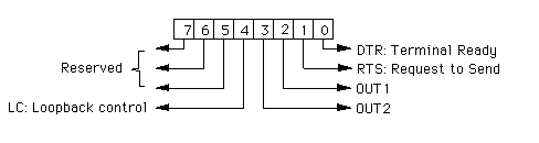
Handshaking protocolThe computer should set DTR=1 when it is ready for communication. (Setting DTR=0, for example, will cause a modem to hang up the telephone line at the end of a transmission.)
RTS=1 indicates that the computer desires to transmit information. Setting RTS=0 would indicate that the modem should turn the line around when using half-duplex mode. For full-duplex mode, RTS should be permanently 1
Modem Handshaking Status
The modem status register (MSR, accessed via port 6), is used to sense incoming signals used for the handshaking RS-232C protocol. All bits in this register are reset to 0 when the register is read, except as noted below.

DSR=1 indicates that the modem is ready for communication. This bit remains 1 after the register is read if the modem remains ready.
CTS=1 indicates that the computer is allowed to transmit information. In half-duplex mode , the modem responds to a signal RTS=1 from the computer by turning the line around and then setting CTS=1. This bit remains 1 after the register is read if the computer is still allowed to transmit information.
CD=1 if the modem believes that there actually is an incoming signal. For example, if a computer is communicating with a remote terminal over a telephone line, and the modem detects that the other party has hung up, it will set CD=0. This bit remains 1 after the register is read if the modem still believes that there actually is an incoming signal.
The modem sets RI=1 when it detects a ringing signal on the telephone line. Thus RI=1 is a request for service from a remote site.
Questions asked during Interview related to UART
Q1 How Rx is working ? When will you sample start bit ?
A.
Q2 Why there is 16x sampling rate ?
A.
Q3 How to match baud rate ?
A.
Q4. Format of UART frame , why stop bit is 1/1.5/2 ?
A
Q5 How baud rate is generated ?
A
Thanks for reading my Blog,please leave your comment if you have any doubt or question.
Table of Contents
Nice Blog , Thanks for sharing Information.
ReplyDelete