Clock Skew
To calculate the Clock skew -
Clock Skew = Clock Arrival time at Capture Flop - Clock Arrival time at Launch Flop.
Here's how it affects Setup and Hold Checks.
Setup Check → Clock_to_Q delay of Launch Flop + Datapath or Combinational logic Delay + Setup-Time of Capture Flop < (Clock Period + Clock Skew)
Hold Check → Clock_to_Q delay of Launch Flop + Datapath or Combinational logic Delay > (Hold-Time of the Capture Flop + Clock Skew).
If you had +200ps clock Skew, then the setup-check gets relaxed by 200ps, but hold-check becomes harder to meet. (And vice-versa if you have -200ps clock skew).
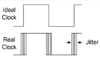
Clock Jitter :
1. Clock Skew
Clock skew refers to the difference in arrival times of the clock signal at different components or registers within a circuit, especially in synchronous systems.
Key Points:
- Clock Skew occurs when the clock signal reaches different parts of a circuit at slightly different times. This can happen due to various factors like differences in the physical routing of the clock signal, variations in the delay through the clock distribution network, or the use of multiple clock sources.
- It is typically measured between two clock edges at different points in the circuit, often between flip-flops or registers.
Effects:
- Setup and Hold Time Violations: Clock skew can lead to timing violations because the data at the destination flip-flop might arrive too early (if skew is too large), causing a setup time violation, or it might be too late, causing a hold time violation.
- Skew can cause data corruption in a synchronous system if the data is not captured at the correct time.
Example:
In a multi-stage pipeline, if one flip-flop in stage 1 receives the clock signal a little later than another flip-flop in stage 2, the clock skew between these flip-flops could lead to synchronization problems.
2. Clock Jitter
Clock jitter refers to small, rapid variations in the timing of the clock signal's edges (both rising and falling edges). These variations occur around the ideal clock period due to noise, variations in the clock source, or environmental factors like power supply fluctuations or temperature changes.
Key Points:
- Clock Jitter is the uncertainty or fluctuation in the timing of the clock signal over time.
- Jitter is typically described by the variance or standard deviation of the clock edges around the ideal time.
- Jitter can be random (due to noise or power supply interference) or deterministic (due to systematic issues like signal coupling or reflections).
Types of Jitter:
- Peak-to-Peak Jitter: The difference between the maximum and minimum times that the clock edges can vary.
- RMS Jitter: The root mean square of the variations in the clock signal over time.
Effects:
- Data Uncertainty: Jitter can cause uncertainty in when data is sampled or clocked into flip-flops, potentially leading to setup or hold violations.
- Signal Integrity Issues: Jitter can reduce the margin of error between signals and affect the performance of high-speed systems.
Example:
If you have a high-speed clock driving a fast communication bus, jitter could cause the timing of the data to be inconsistent, affecting synchronization and leading to incorrect data capture at the receiving end.
Key Differences Between Clock Skew and Clock Jitter
| Aspect | Clock Skew | Clock Jitter |
|---|---|---|
| Definition | The difference in arrival times of the clock signal at different points in the circuit. | The random or periodic variation in the clock signal's edges over time. |
| Cause | Caused by variations in the routing of the clock signal or the use of different clock sources. | Caused by noise, power supply variations, temperature fluctuations, or interference. |
| Type | Static (it remains constant during operation). | Dynamic (it fluctuates with time). |
| Effect on System | Can cause setup or hold time violations between registers or flip-flops in a synchronous system. | Can cause timing uncertainty leading to data errors, affecting the accuracy of data capture. |
| Measured as | The difference in arrival times of the clock signal at two or more points. | The variation (usually in terms of rms or peak-to-peak) of the clock edges over time. |
| Example | A clock signal arriving at one flip-flop 1 ns later than at another. | A clock signal's rising edge being delayed randomly by ±0.2 ns due to noise. |
How They Impact Timing and System Design:
- Clock Skew is generally a static issue and can be mitigated by proper clock tree design or balancing the clock distribution network.
- Clock Jitter is a dynamic issue that can be reduced by improving signal integrity (e.g., using better clock sources, decoupling power supplies, reducing noise), but it is harder to completely eliminate due to its inherent nature.
Summary:
- Clock Skew: Static timing difference between clocks at different points in the circuit.
- Clock Jitter: Dynamic variation in the timing of the clock signal's edges over time.
Both skew and jitter can negatively affect a system's performance by introducing timing errors, so they need to be minimized through careful circuit and timing analysis, especially in high-speed designs.
Let me know if you'd like more details on how these issues are handled in specific designs or any other related concepts!
Which has better career growth, back end vs front end VLSI ?


No comments:
Post a Comment